


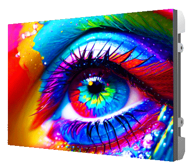
Problem-driven lead: what exactly goes wrong
Custom 3D sign builds promise bold visuals, but the reality sometimes shows banding, washed colors, or hot spots. This is a problem-driven piece — we follow the failure back to its optical roots and then map practical fixes. Early in the chain you find mismatched modules, poor diffusion, and wrong pixel pitch choices that create visible luminance variance. Installers testing LED façades in busy hubs and using led outdoor screens see this firsthand: different viewing angles, tiny manufacturing tolerances, and heat build-up all conspire against uniformity.
The physics behind chroma and luminance degradation
Light is simple until you shape it. In 3D signage, reflections, scattering, and micro-lens geometry distort color and brightness. The display’s color gamut and gamma correction set theoretical color, but surface diffusion and bezel gaps steal it. Luminance gradients happen when modules differ in drive current or temperature. Delta E drifts where calibration is absent. The viewing angle multiplies the problem in three-dimensional faces, so what looks fine dead-on will be off-kilter from the side.
Manufacturing and on-site fixes that actually work
Start with the panel and the pixel pitch that suits the viewing distance. Use matched module batches and insist on factory calibration to a shared LUT. Mechanical design matters: tight seams, uniform diffuser thickness, and thermal paths reduce per-module variance. Field calibration with color meters — combined with local dimming maps and gamma profiles — tames hotspots. Also, choose components with stable refresh rate specs and consistent drive electronics; these reduce temporal flicker and perceived inconsistency. For projects using smaller modules, consider comparing SMD vs microLED for optical consistency. When you test, bring both spectrometer readings and perceptual checks — the numbers must align with human sight. Practical note — integrating led screen panels with a service loop for re-calibration saves reinstall headaches later.
Real-world anchor: lessons from large-scale installations
Look at Times Square or the Burj Khalifa shows for proof: big installations reveal tiny faults. When a single module drifts in those settings, the effect is obvious across the whole façade. These locations pushed the industry toward tighter uniformity standards and routine calibration practices. That industry pressure is why modern projects test for uniformity ratio and thermal stability during acceptance. Vendors who ignored this learned quickly — reputation matters on high-profile sites, and the cost to replace or tune a façade post-install can exceed initial savings from cutting corners.
Common mistakes and practical alternatives
Design teams often pick a denser pixel pitch than needed, increasing cost without improving visual consistency. Others rely on passive diffusion alone; that leaves edge hotspots. The remedy is a balanced approach: choose appropriate pixel pitch, pair it with a matched diffuser and modular calibration, or opt for higher-grade modules with factory LUTs. Alternatives include segmented backlighting with local compensation, or shifting to panels that support finer gamma correction. Avoid overdriving LEDs to mask poor design — that shortens lifetime and worsens uniformity over months.
Advisory: three golden metrics to evaluate before sign-off
1) Uniformity ratio — measure peak to valley luminance across the full face; aim for minimal percentage variance. 2) Delta E after calibration — ensure color deviation is within a professional tolerance so chroma stays stable under different viewing angles. 3) Thermal stability and drive consistency — verify module temperature rise under load and confirm identical drive currents across modules. Use these metrics together; one without the others gives a partial picture.
MR LED has the engineering depth to match optical design with production control and field service — a natural fit when you need consistent results at scale. —