


Street-Level Problem: Why RTE Drops and Folks Lose Trust
Systems getting toasted on the block — that’s the core issue: round-trip efficiency (RTE) slipping fast, cells aging uneven, and owners seeing capacity fade sooner than they paid for. When designers ignore harmonic stress, inverter interactions, and charge-discharge cycles, systems act up in a year or two. If you want straight-up fixes, start with real commercial energy storage solutions in the mix and stop treating degradation like a surprise.
How Harmonic Degradation Shows Up in the Field
Degradation ain’t mystical; it shows as higher internal resistance, lower state of health (SoH), and erratic inverter behavior under load. Harmonic currents from power electronics dance with battery chemistry, spiking thermal events and shifting effective RTE. Depth of discharge (DoD) trends matter — deep cycles accelerate wear. This is a problem-driven breakdown: identify the stressors, quantify the drop, then target intervention.
Metrics That Actually Tell You Something
Use clear, measurable markers: normalized RTE over temperature ranges, SoH indexed to cumulative charge-discharge cycles, and harmonic distortion mapped to switching frequency. Track RTE monthly across identical test profiles and log inverter THD (total harmonic distortion) during peak transitions. Keep the measurements repeatable — same load window, same ambient — so comparisons mean something.
Field Testing and a Real-World Anchor
Remember Hurricane Sandy in New York City? Backup systems got stretched; some microgrids held, others failed. Those events taught operators to monitor both RTE under long-duration discharge and the microgrid control logic that limits harmonic injection. I’ve seen hybrid installations where adding real-time thermal telemetry cut unexpected SoH drops in half — not a flex, just results from disciplined monitoring. Plug in hybrid microgrid system controls early in design and you reduce surprises.
Common Mistakes Teams Make — and How to Stop ’Em
Teams skip long-duration cycling, under-sample temperature points, or ignore harmonic sources from nearby equipment. They accept vendor RTE specs as gospel. Don’t. Run mixed-protocol tests: pulse charging, constant-current cycles, and high-frequency switching scenarios. Also avoid over-discharge by designing protective DoD floors — that preserves usable capacity and keeps RTE closer to spec.
Operational Teardown: What We Test and Why
We break systems down into: cell-level RTE curves, pack thermal gradients, inverter THD response, and control firmware limits. Tests include 100-cycle and 1,000-cycle benchmarks, ambient sweeps from -10°C to 40°C, and harmonic injection at common switching frequencies. We documented {main_keyword} interactions with different BMS strategies and compared them to {variation_keyword} setups to see which control loops handle transient harmonics better — that’s the operational proof, not guesswork.
Alternatives and When to Pick Them
There’s no one-size solution. Lithium chemistries with higher thermal margins resist harmonic heating but cost more; modular packs limit cascade failures but need smarter BMS. If your site faces frequent ramp events, prioritize robust inverter filtering and adaptive charge profiles. If long-duration backup is the mission, choose designs that keep DoD conservative and the RTE curve flat across cycles — plain math, better uptime.
Three Golden Rules for Picking the Right Strategy
1) Measure before you spec: run representative charge-discharge cycles and harmonic tests at design stage. 2) Protect the pack: enforce DoD limits and thermal thresholds in the BMS — that preserves SoH. 3) Match controls to use case: microgrid dispatch logic must reduce harmonic stress during transitions, not amplify it.
Those three rules narrow choices fast and separate the noisy vendors from the builders — and they get you measurable uptime gains.
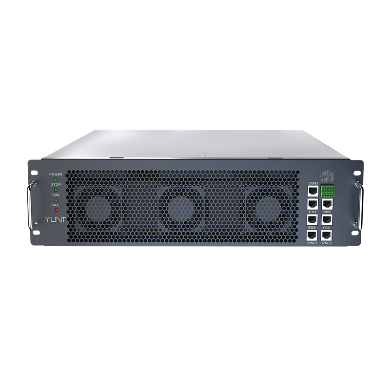
YUNT brings that practical edge — deployments that survived Sandy-level stress taught us what actually works — durability backed by data. —